GPIO Control
FlexKVM provides two independent GPIO pins for connecting external hardware — switches, sensors, relays, etc. — for input detection or output control.
⚠️ Pin voltage is 3.3V. Do not connect 5V or higher-voltage devices — this will damage the device.
For industrial control, custom hardware integration, and other specialized scenarios. Regular users typically don't need this.
Before You Begin
| You need | Notes |
|---|---|
| FlexKVM | Completed Quick Start wiring and network setup |
| 2.54mm Dupont wires (female) | For connecting to GPIO pins |
| External device | Switches, sensors, relays, etc. — must support 3.3V logic level |
Pinout
Two independent GPIO pins with letter labels:
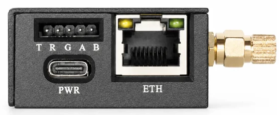
| Silkscreen | Pin | Description |
|---|---|---|
| G | GND | Ground — common ground with external device |
| A | GPIOA | General-purpose I/O, independently configurable |
| B | GPIOB | General-purpose I/O, independently configurable |
Wiring Examples
Reading a Switch (Input Mode)
GPIOA ──┬── Button one end
        │
GND ────┴── Button other end
Button pressed → GPIOA reads low; released → high (internal pull-up by default).
Controlling an LED (Output Mode)
GPIOB ────→ Current-limiting resistor ────→ LED anode (long leg)
GND ──────────────────────────────────────→ LED cathode (short leg)
The LED needs a 220Ω ~ 1kΩ current-limiting resistor in series, otherwise the LED or GPIO may be damaged.
Software Configuration
Top bar → click chip icon → IO menu → GPIO Control.
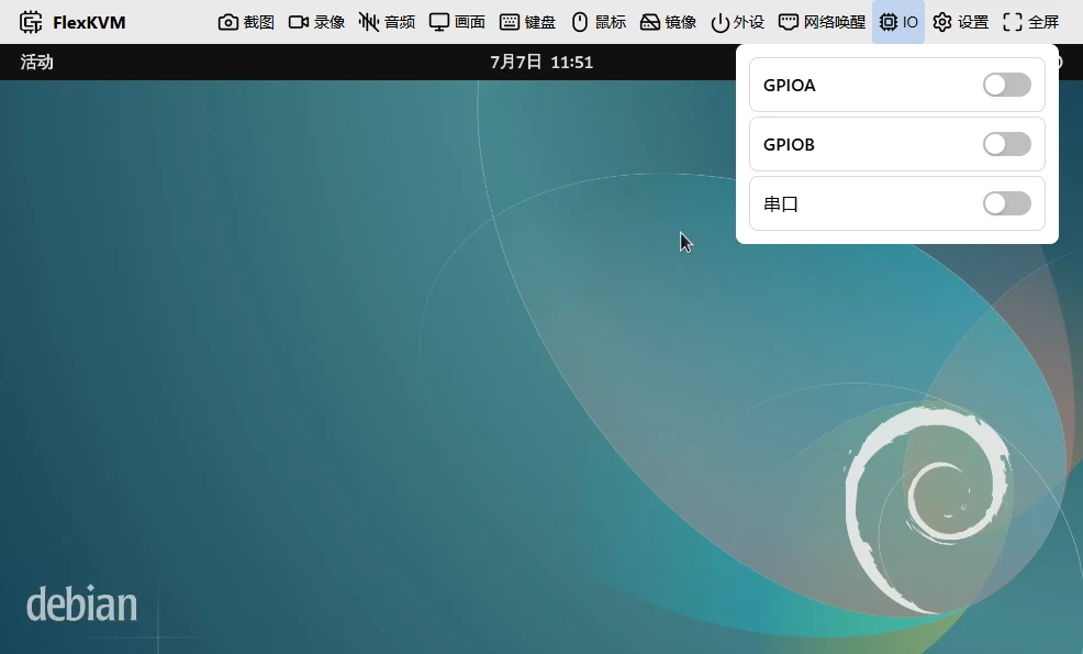
All pins are disabled by default (input mode, not monitoring). You need to enable them manually.
Enable a Pin
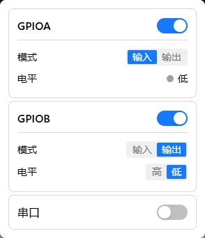
Each pin card has a toggle. When enabled, the pin enters input mode and starts monitoring the level.
Input Mode
The pin level is determined by the external device — the interface reflects it in real time:
- 🟢 Green = High (3.3V)
- ⚫ Gray = Low (0V)
In input mode, you cannot manually set the level. External changes auto-update in the interface.
Output Mode
Click the mode toggle button → manually control via "High"/"Low" buttons:
- High → pin outputs 3.3V
- Low → pin outputs 0V
Switch back to input mode when you need to read external signals.
FAQ
No voltage on output? → Confirm the pin is enabled and the mode is "Output". Enabling alone keeps it in input state.
Reading wrong level? → Check wiring and confirm common ground (GND connected) with the device.
Interface doesn't update after wiring? → Make sure the pin is enabled. Disabled pins don't monitor level changes.