Interface Reference
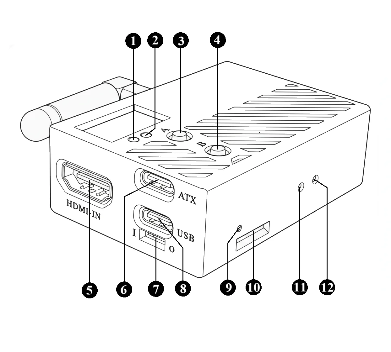
- [1] Warning LED
- [2] Status LED
- [3] Button A
- [4] Button B
- [5] HDMI Input
- [6] ATX Port
- [7] USB Power Switch
- [8] USB Port
- [9] Power LED
- [10] TF Card Slot
- [11] Factory Reset Button
- [12] Reset Button
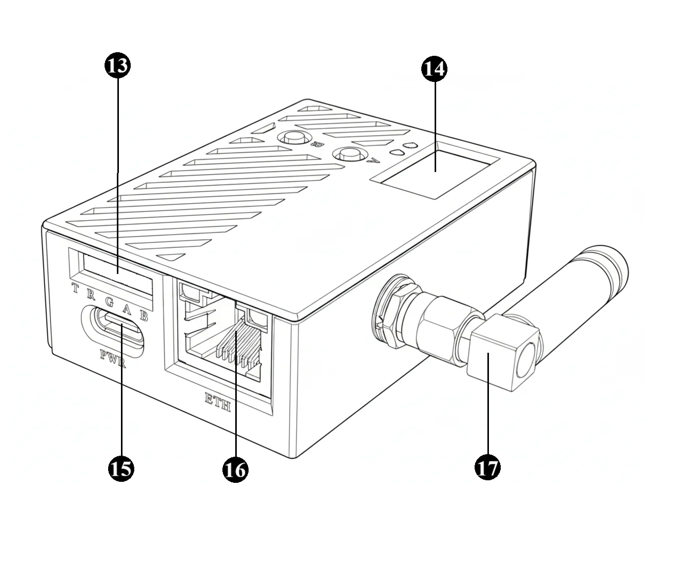
- [13] Expansion Port
- [14] OLED Display
- [15] Power Port
- [16] Ethernet Port
- [17] WiFi Antenna
Indicators
FlexKVM has three indicator LEDs showing power, connection, and network status. For detailed status information, see LED Indicators.
| # | Name | Color | Basic description |
|---|---|---|---|
| [1] | 🔴 Warning LED | Red | Reflects network and system status |
| [2] | 🟢 Status LED | Green | Reflects device connection status |
| [9] | 🔴 Power LED | Red | On = powered, Off = not powered |
Buttons
FlexKVM has four physical buttons. For detailed operation, see Physical Buttons.
| # | Name | Basic function |
|---|---|---|
| [3] | Button A | Press and hold 1–3s to enter hotspot provisioning mode |
| [4] | Button B | Hold 3–5s to toggle WiFi ↔ AP mode |
| [11] | Factory reset button | Hold 15s to restore factory settings |
| [12] | Reset button | Press briefly to force a reboot |
HDMI Input
- Spec: Standard HDMI Type-A, HDMI 1.4 compatible.
- Function: Receives HDMI video signal from target host, up to 1920x1200@60fps.
ATX Port
- Spec: USB Type-C.
- Function: Connects to ATX controller for remote power on/off, force reboot, and normal shutdown.
USB Port
- Spec: USB Type-C, USB 2.0 data/OTG.
- Function: Establishes keyboard/mouse control and data transfer channel with target host.
USB Power Switch
- Spec: Toggle switch.
- Function: Controls power input from the USB Data port. Set to ON to allow the USB Data port to power the entire device; set to OFF to disable power input from this port.
TF Card Slot
- Spec: Micro SD (TF) card slot.
- Function: For virtual USB drive ISO mounting and local storage expansion.
Expansion Port
- Spec: 5-pin 2.54mm header.
- Function: Provides UART serial communication and GPIO control. Pin labels are printed beside each pin.
Caution: Interface logic level is 3.3V. Do not connect 5V signals — this will damage the device.
| Label | Name | Function |
|---|---|---|
| T | UART TXD | Serial data transmit |
| R | UART RXD | Serial data receive |
| G | GND | Ground |
| A | GPIOA | General-purpose I/O |
| B | GPIOB | General-purpose I/O |
Display
- Spec: Monochrome OLED, 128x64 resolution.
- Function: Shows device network status, IP address, AP provisioning info, and current operating mode. See OLED Screen.
Power Port
- Spec: USB Type-C.
- Function: 5V/1A or higher input, powers the device.
Ethernet Port
- Spec: RJ-45, 10/100M auto-negotiation Ethernet.
- Function: Wired network access.
WiFi Antenna
- Spec: SMA male, dual-band 2.4GHz / 5GHz.
- Function: Connects to external WiFi antenna for wireless network access.